Views: 5357 Author: James Wu Publish Time: 2021-01-15 Origin: Site
Both SPI and UART are chip units that process and transmit data. However, SPI (Serial Peripheral Interface) is usually a 3 - 4 wire interface, which can send and receive independently and can be synchronized, while UART (Universal Asynchronous Receiver Transmitter) has only one input port and one output port, which completes two-way communication at the standard baud rate.
SPI is a high-speed, full-duplex, and synchronous communication bus; SPI is also a data exchange protocol, since SPI's data input and output lines are independent, it allows simultaneous data input and output. Unlike ordinary serial communication, SPI allows data to be transmitted bit by bit, and even pauses. Because the SCK clock line is controlled by the master device, when there is no clock jump, the slave device does not collect or transmit data. In other words, the master device can complete the control of communication by controlling the SCK clock line. However, the SPI interface also has a shortcoming: it has no specified flow control and no response mechanism to confirm whether data is received.

UART is a universal serial data bus used for asynchronous communication. This bus has two-way communication and can realize full-duplex transmission and reception. In embedded design, UART is used for communication between host and auxiliary equipment, such as communication between car audio and external AP. Communication with PC includes communication with monitoring debugger and other devices, such as EEPROM
The structure of UART is much more complicated than that of SPI. Generally, it consists of a baud rate generator (the generated baud rate is equal to 16 times the transmission baud rate), a UART receiver, and a UART transmitter. The hardware consists of two wires, one for transmitting, one for receiving. Obviously, if an universal IO port is used to simulate a UART bus, one input port and one output port are enough.
UART is often used to control chips in computers and serial devices. One thing to note is that it provides an RS-232C data terminal device interface so that the computer can communicate with modems or other serial devices that use the RS-232C interface. As part of the interface, UART also has the following functions:
1. Convert the parallel data transmitted from the computer into the output serial data stream.
2. Convert the serial data from the outside of the computer into bytes for use by the devices that use parallel data inside the computer.
3. Add a parity bit to the output serial data stream, and perform a parity check on the data stream received from the outside.
4. Add the start-stop mark to the output data stream, and delete the start-stop mark from the received data stream.

There are also big differences between SPI and UART on electrical signal lines:
The communication principle of SPI is very simple. It works in a master-slave mode and usually consists of a master module and one or more slave modules. The master module selects a slave module for synchronous communication to complete data exchange.
SPI has two modes, Normal Mode and Bi-directional Mode, including the following lines:
1. SS: Slave Select
2. SCK: Serial Clock
3. MOSI: Master Output, Slave Input
4. MISO: Master Input, Slave Output
5. MOMI: Master Output, Master Input
6. SISO: Slave Input, Slave Output
Among them, the first four wires are used for Normal Mode, and the normal mode of 4 wires is also commonly used.

MOSI: this pin is used to transmit data out of the SPI module when it is configured as a Master and receive data when it is configured as Slave.
MISO: this pin is used to transmit data out of the SPI module when it is configured as a Slave and receive data when it is configured as Master.
SS: this pin is used to output the select signal from the SPI module to another peripheral with which a data transfer is to take place when its configured as a master, and it is used as an input to receive the slave select signal when the SPI is configured as Slave.
SCK: this pin is used to output the clock with respect to which the SPI transfers data or receive clock in case of Slave.
Note:
1. Some times, 3 wires are also available for unidirectional transmission.
2. The SCK signal line is only controlled by the master device, and the slave device cannot control the signal line.
3. Similarly, in an SPI-based device, there is at least one master device.
The SPI includes these distinctive features:
1. Master mode and slave mode
2. Bi-directional mode
3. Slave select output
4. Mode fault error flag with CPU interrupt capability
5. Double-buffered data register
6. Serial clock with programmable polarity and phase
7. Control of SPI operation during wait mode
In short, both SPI and UART can achieve full duplex, but SPI implementation is simpler. After all, UART requires a fixed baud rate, which means that the interval between two data bits must be equal, while SPI does not matter because it is a clocked protocol.
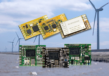
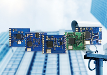
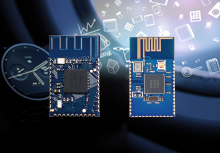
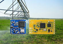
As a professional RF module supplier, DreamLNK offers various RF modules, like 2.4G RF modules, FSK transceiver modules, Bluetooth modules, LoRa modules, most of them adopt SPI interface, but some also adopt UART interface. Welcome to inquire!