Views: 3274 Author: James Wu Publish Time: 2021-10-16 Origin: Site
In the process of R&D and debugging of RF modules, customers often encounter communication distance problems. How do we investigate and optimize the RF performance of our products? Let's take a real case as an example, and do a simple analysis for you here, hope it helps you in some way.

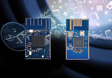
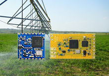
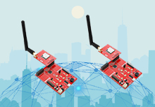
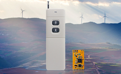
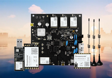
Products: RF Module (DL-RTS4463) + Spring Antenna (DL-T1)
Frequency: 915 MHz
Bit Rate: 100Kbps
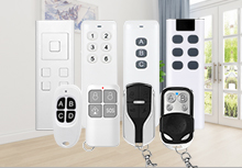
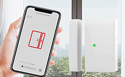
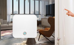
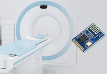
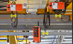
Application: remote control of the automatic shutter
Feedback: communication distance is too close, only 70M
Current status of design: direct connection between RF Module and antenna (see below); metal housing shield at receiving end

Solution: change the metal housing shield into a plastic cover; reduce the bit rate to 10Kbps; add a π-type circuit between the antenna DL-T1 and DL-RTS4463 RF module (for RF matching)
In addition, the following factors that may affect the RF communication distance need to be investigated and improved one by one:
* Wireless Switching Logic Control (Software): TX_EN=1 and RX_EN=0 are guaranteed when sending; and vice versa when receiving (TX_EN=0 and RX_EN=1). If this mutually exclusive relationship is not observed, the communication distance will be greatly reduced.
* Wireless Configuration (Bit Rate): when considering long distance communication, the bit rate needs to be as low as possible, preferably below 10 kbps
* Wireless Configuration (Modulation): the configuration table for radio frequency initialization is best generated by software with the highest power setting. In long range mode under FSK Modulation, the following conditions must be met:
Bandwidth > 2 * Frequency Deviation (F(Dev)) + Information Bit Rate
* Receiving Sensitivity: away from high frequency clutter, such as high power motor, power supply, high frequency circuit, etc.
* External Factors: the transmission path must not have metal (e.g. metal housing/cover, etc.)

Finally, through the efforts of both engineers and repeated debugging of π-type circuit parameters, the communication distance of the product improved a lot. We hope that the above cases will have some inspiration for your RF product development.
As an RF Module and Antenna solution provider, DreamLNK has specialized in radio frequency field for almost 8 years. If you have any requirement for RF modules and antennas, please do not hesitate to contact me james@dreamlnk.com!