

DreamLNK
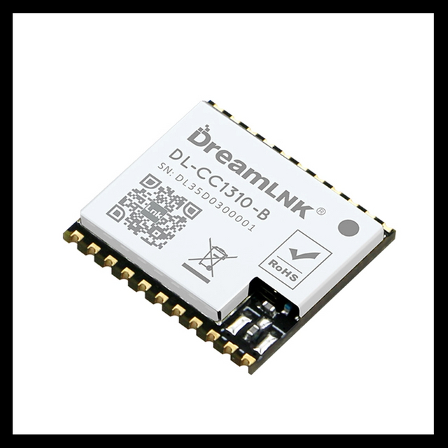
DL-CC1310-B868 (915)
868Mhz/915Mhz
CC1310
14dBm
1.8~3.8V
-124dBm
800m
18*16*2mm
| Availability: | |
|---|---|
| Quantity: | |
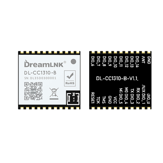
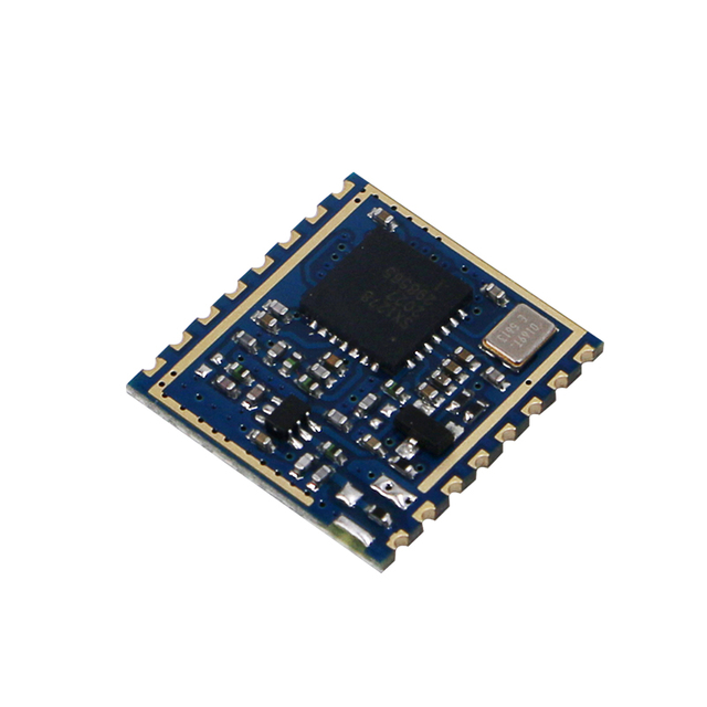
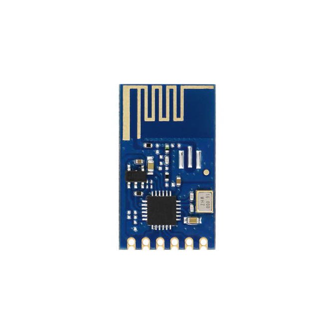
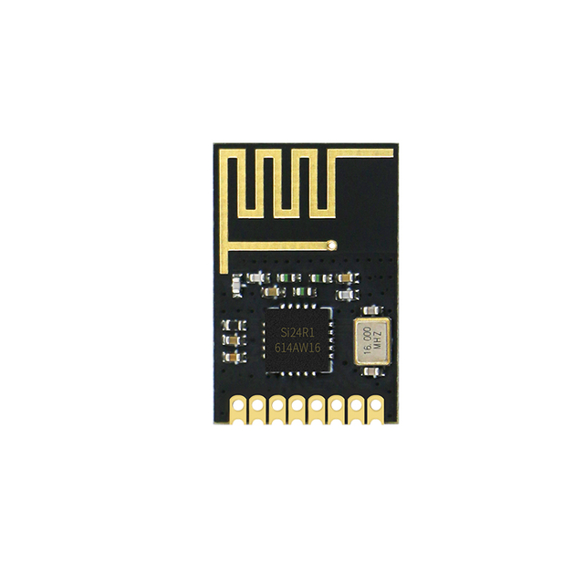
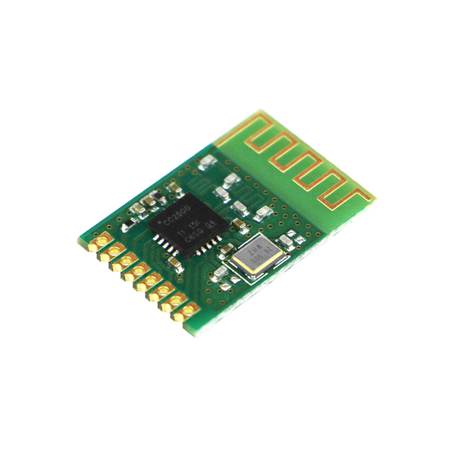
FCC CE & UKCA Audit Passed 868Mhz/915MHz Wireless Transparent SoC Transceiver Module (TI CC1310 Chip)
DL-CC1310-B Wireless Module is a SoC Transceiver Module (UART Module) with AT command, which was developed based on Texas Instruments' CC1310F128RHBR (built-in dual-core ARM) Radio Frequency chip. It combines an integrated RF Controller (Cortex®-MO) and a powerful Arm® Cortex®-M3 Processor, the Clock Speed of the MCU can reach up to 48MHz.
This DL-CC1310-B Wireless Module supports Narrow-band Communication, Direct Sequence Spread Spectrum (DSSS), Long-range Transmission and High-efficiency Communication. It has built-in fully functional AT Commands that support any Serial Baud Rate setting from 1920bps to 256000bps, which can greatly improve the communication efficiency with up to -124dBm receiving sensitivity.
The embedded software makes this Wireless Module support not only Transparent Transmission Mode, Accurate Signal Strength Indication, automatic CCA (Clear Channel Assessment), but also High-speed Data Stream & Packet Segmentation Transmission, which can effectively reduce the probability of signal collision.
Moreover, it has defaulted low power consumption software, as well as other muti-functions serial port programs when it is manufactured. A variety of Wireless Baud Rates and functions can be configured, including Long-range Spread Spectrum Mode and Universal Mode, Wake-on-Radio (eWOR) function, etc. These different configurations can provide simple and efficient solutions for various long-range communication and IoT applications.
All these features above makes this DL-CC1310-B Wireless Module to an excellent RF performance and strong anti-interference in the 420-510MHz/860-950MHz frequency band. It combines a flexible, very low power RF transceiver with a powerful MCU in a platform supporting multiple physical layers and RF standard, which is ideal to use especially for battery power applications. You can also make secondary development based on TI’s development Kit if needed.
Hardware Features:
● Original CC1310 Chip from TI;
● SOC integrated RF module with metal shield
● Industrial grade components: 433/868/915MHz
● Wide supply voltage range: 1.8V to 3.8V;
● Ultra-low sleep current < 1uA;
● High efficiency receiving performance (RX current @ 5.5mA);
● High Transmission Efficiency:
TX (+10dBm): 17mA;
TX (+14dbm): 27mA;
● Excellent Receiver Sensitivity:
Long Range Mode: -124dbm at 0.625kbps;
Universal Mode: -110dbm at 50kbps;
● Accurate Signal Strength Indication and Clear Channel Assessment (CCA).
● Compact size for SMD mounting (Dimensions = 18x16.5mm)
Software Features:
● Easily configure with AT command, for a simple development;
● Transparent Transmission Mode supported;
● Data flow control & high-speed data stream transmission supported;
● 1920-256000bps serial baud rate is supported;
● 0.6kbps-500kbps wireless baud rate is supported;
● Wake-on-Radio (eWOR) function supported, which can be greatly increases the battery standby time;
● Packet Segmentation Supported
● Preset CCA (Clear Channel Assessment) function, which can effectively reduce the collision probability of co-frequency interference;
● Strong Anti-jamming: supports anytime RSSI acquisition and CCA (Clear Channel Assessment);
● Supports manual fast frequency hopping to avoid co-frequency interference;
● Point-to-Point, Broadcasting and Monitoring transmission can be achieved.
● Remark: there are 3 Versions available
- DL-CC1310-B-433 433Mhz Transparent UART Module: Frequency @ 433MHz
- DL-CC1310-B-868 868MHz Transparent UART Module: Frequency @ 868MHz
- DL-CC1310-B-915 915MHz Transparent UART Module: Frequency @ 915MHz
Download Center
DL-CC1310-B Specification V1.12
Technical Parameter
Parameter | Min. | Typical | Max. | Unit | Remarks |
Operating Conditions | |||||
Working Voltage | 2.0 | 3.3 | 3.6 | V | Voltage above range may damage the RF module |
I/O Voltage Range | 1.8 | 3.3 | 3.6 | V | Recommended operating voltage is +3.3V |
Working Temperature Range | -40 | 25 | 85 | ℃ | |
Current Consumption | |||||
Receiving Current | 5 | 5.5 | 6.1 | mA | @ Radio Frequency Receiving Current (MCU sleep) |
Receiver Working Current | 6 | 6.8 | 8 | mA | @ Overall Receiving Current |
Transmission Current | 32 25 15 | 35 27 17 | 38 29 20 | mA | @433M 15dBm Peak value @433M 14dBm Peak value @433M 10dBm Peak value |
27 16 | 29 18 | 32 21 | mA | @868M 14dBm Peak value @868M 10dBm Peak value | |
27 16 | 29 18 | 32 21 | mA | @915M 14dBm Peak value @915M 10dBm Peak value | |
Standby Current | 1 | 1.5 | 2 | mA | @ Radio Frequency Receive Function Stopped |
Sleep Current | 0.2 | <1 | 2 | uA | @M1=0 |
RF Parameters | |||||
Recommended Frequency (Ensure best performance)) | 420 | 433 | 510 | MHz | @433Mh RF module |
840 | 868 915 | 930 | MHz | @868Mhz/915Mhz RF module | |
Transmitting Power Range | -10 | 14 | 15 | dBm | @0-10dBm, 1dbm resolution |
Max. Receiver Sensitivity @ FSK | -120 | -124 | -127 | dBm | @868Mhz/915Mhz @625bps |
-119 | -122 | -124 | dBm | @433Mhz @625bps | |
FSK Rate Range | 0.625 | 9.6 | 500 | Kbps | @ See Recommended Configuration for details |
Wake-on-Radio Mode Consumption | 0.04 | mAH | @AT+RXGAS=500 | ||
Recommended Configuration
Rate (bps) | Focus on | Clear Channel Threshold Setting | Recommended Channel Spacing | WOR Function |
625 | Range optimization | -92 dBm | 250Khz | Not Available |
1250 | Range optimization | -92 dBm | 250Khz | Not Available |
3750 | Range optimization | -92 dBm | 250Khz | Not Available |
2500 | Range optimization | -92 dBm | 250Khz | Not Available |
5000 | Range optimization | -92 dBm | 250Khz | Not Available |
2400 | Common mode | -92 dBm | 250Khz | Available |
3600 | Common mode | -90 dBm | 250Khz | Available |
6200 | Common mode | -90 dBm | 250Khz | Available |
9600 | Common mode | -90 dBm | 500Khz | Available |
14400 | Common mode | -85 dBm | 500Khz | Available |
19200 | Common mode | -85 dBm | 500Khz | Available |
25000 | Common mode | -85 dBm | 500Khz | Available |
38400 | Common mode | -85 dBm | 500Khz | Available |
50000 | Common mode | -80 dBm | 500Khz | Available |
70000 | Common mode | -80 dBm | 500Khz | Not recommended |
100000 | Common mode | -80 dBm | 500Khz | Not recommended |
200000 | Common mode | -75 dBm | 1Mhz | Not recommended |
300000 | Common mode | -75 dBm | 1Mhz | Not recommended |
400000 | Common mode | -75 dBm | 1Mhz | Not recommended |
500000 | Common mode | -75 dBm | 1Mhz | Not recommended |
Product Size
Pin Definitions:
Pin Name | I/O Type | Pin Description |
VCC | PWR | To maximize the chip function, ≥2.5V stable voltage is recommended |
GND | PWR | Reference Ground |
ANT | Analog I/O | RF signal input/output port, π-matching network must be reserved; Adopt 50Ω impedance matching for RF routing, route the ground and add via holes around it |
DIO1(AUX) | Out | Indicate the working status of the module:
Start-up initialization or wake-up mode initialization: 0: Initialization completed; serial port transmission can be carried out 1: Serial port transmission is not allowed until initialization is completed
AT Command: 0: Idle 1: TX buffer is full and needs to wait for low level before transmission
Transparent Transmission Mode & Wake-on-Radio (WOR) Mode: 0: Idle 1: The module receives the data and outputs the data through the serial port after the set delay
When Transmitting Data to the Module: 0: The buffer is empty (Transmitting completed) / the buffer is not full 1: Buffer is not empty / buffer full, (Two settings can be configured by “AT+ AUXM” Command) |
DIO2(UART-RX) | In | TTL serial port output, connected to external RXD input pin |
DIO3(UART-TX) | Out | TTL serial port input, connected to external TXD output pin |
DIO4(M0) | In | Switching between AT Command and Transparent Transmission Mode, defaulted high level 0: Transparent Transmission Mode 1: AT Command Mode |
DIO5(M1) | In | Control Module Sleep, defaulted high level 0: Sleep (or wake-on-radio) 1: Wake up |
DIO6-DIO14 | Out / In | Common I/O port, no function at present, can be customized to realize the following functions: 1. ADC detection 2. Key value fast transmit 3. RF status indication 4. PA control If not used, it must be N/C (No Connection) |
Typical Applications
Wireless Data Communication, Wireless Data Monitoring and Transmission, Wireless Voice/Audio Transmission, Wireless Sensoring; Wireless Remote Control System; Wireless Game Controller, Remote Control Toys; Wireless remote control for electronic consumer products; Wireless Alarm & Security Control System; Wireless Sensor Networking, Automatic Data Collection; Industrial Remote Control, Intelligent Control System, Home Automation, Home Appliance Control, Building and Residential (smart home) Control, Smart City, RFID (radio frequency identification); Telemetry, Automatic (Water, Electricity, Gas) Meter Reading system; Remote control that supports radio frequency (RF) technology
What is Wireless Transparent UART Module?
Simply speaking, it is an RF module that can communicate wirelessly through its serial port. We don't need to care about its complex wireless parameters, but only need to transmit and receive the data (to be processed) through the serial port, which can greatly save the development cost and shorten the development cycle.
Product Tags
UART Serial Module, Radio Transmitter Module, RF modules, RF Transmitter, RF Transmit module, Wireless Transmitter Module, ASK Transmit Module, RF Transmitter Module, Wireless Module
DREAMLNK TECHNOLOGY CO., LTD. ALL RIGHTS RESERVED|SITEMAP
