|
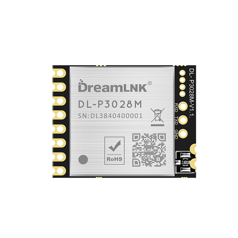


DL-P3028M
DreamLNK/骏晔
DL-P3028M
398~510MHz
PAN3028
22dBm
1.8~3.6V
-140dBm
3000m
26*20.5*3.5mm
| Quantity: | |
|---|---|
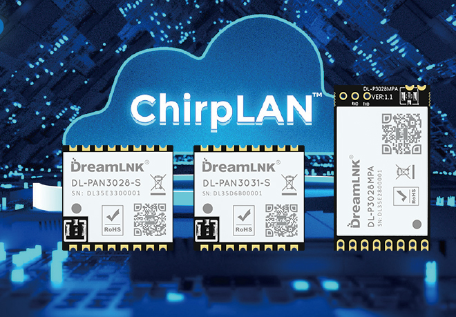
Brief Introduction
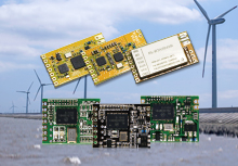
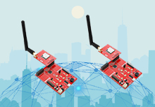
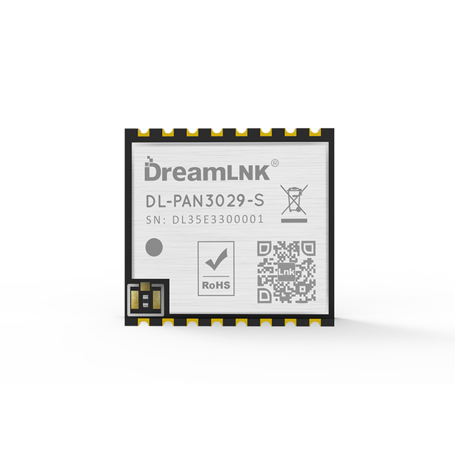
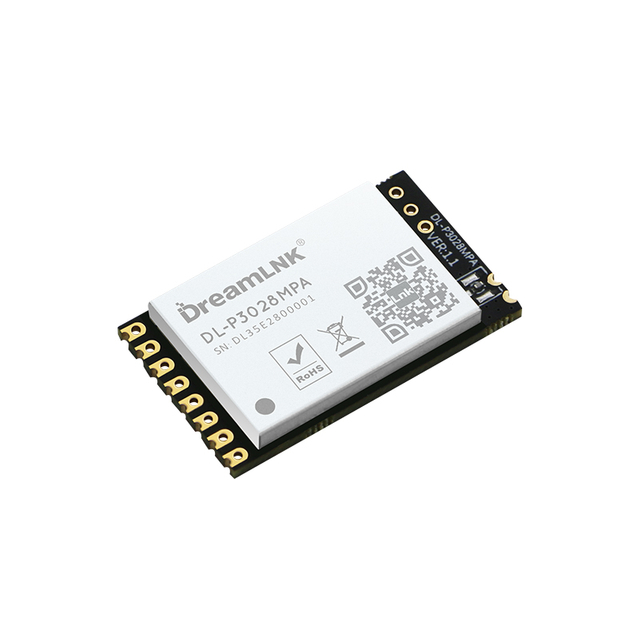
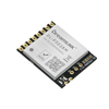
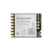
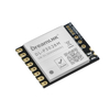
This DL-P3028M RF module is an UART Transceiver Module, which was designed base on high-performance PAN3028 RF chip and built-in HC32L130 low-power MCU. It is an UART Module with AT command, which supports a maximum power output of 22dBm and a sensitivity of -140dBm; it is an effective wireless module which can provide excellent RF performance and strong anti-interference performance in the 398-510MHz frequency band.
Features
● Support AT commands for configuration, easy to develop and debug;
● Support transparent transmission mode for data transmission;
● Support data flow control in transparent transmission mode (AUX);
● Typical serial baud rate (such as 9600/19200/38400/57600/115200bps) is supported;
● Multiple wireless baud rate is supported;
● Wake-on-Radio (WOR) function supported (intermittent receiving), which can be greatly increases the battery standby time;
● Support CAD (Automatic Radio Frequency Signal Detection) to reduce the probability of signal collision;
● Can achieve fixed point transmission, broadcasting and other transmission methods;
Download Center
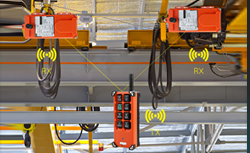
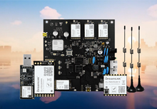
Typical Application
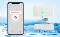
● Smart Grid and Automatic Meter Reading (water meter, electricity meter, gas meter)
● Long-Range Data Communication
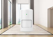
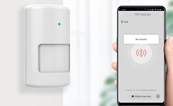
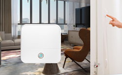
● Smart Home Systems
● Wireless Sensor Networks
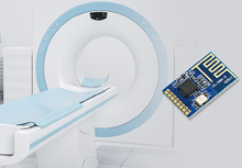
● Industrial Automation (Data Acquisition)
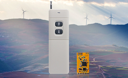
● Remote Control and Telemetry of Field Data
● Various Transmitter, Intelligent Flow Meter Instrument
● Building Automation and Security
● Monitoring and Control of Petroleum Equipment in Mines
● Environment, Energy Saving, Temperature Monitoring
● Intelligent Transportation, Smart City
● Home and Building Automation
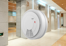
● Wireless Alarm and Security System
Technical Parameter
No. | Category | Parameter | Value |
1 | Radio Parameter | Working Frequency | 398~510MHz |
2 | Radio Parameter | TX Power | 22dBm (peak value) |
3 | Radio Parameter | RX Sensitivity | -140dBm @SF12 62.5KHz -133dBm @SF9 62.5KHz |
4 | Radio Parameter | Communication Range | (1) >300M@SF7, BW250khz, RF power:22dBm (2) >1500M@SF9, BW125khz, RF power: 22dBm |
5 | Radio Parameter | Antenna Type | External antenna (ANT pad or IPEX) |
6 | Hardware Parameters | Data Interface | Baud rate: 115200 (default) |
7 | Hardware Parameters | Working Voltage | 1.8~3.6V |
8 | Hardware Parameters | Working Current | Receiving: 24mA Sleeping: 1.6uA |
9 | Hardware Parameters | Working Temperature | -40℃ ~ +85℃ |
10 | Hardware Parameters | Storage Temperature | -45℃ ~ +90℃ |
11 | Hardware Parameters | Encapsulation Interface | SMT (surface mount) |
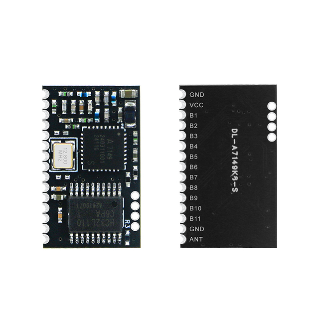
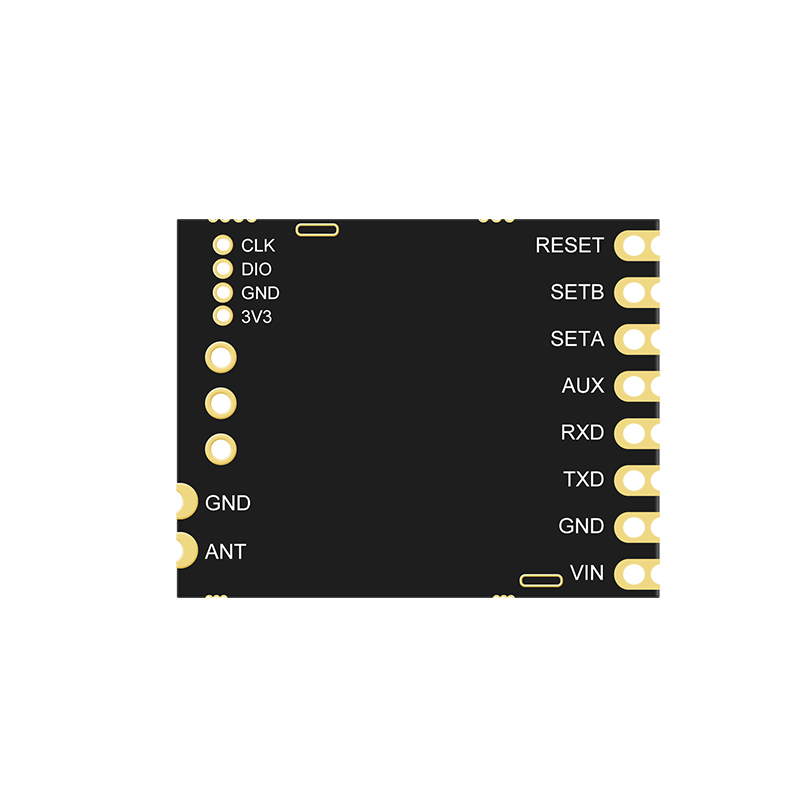
Pin Definitions

| No | Definitions | Type | Description |
| 1 | VIN | PWR | To maximize the chip function, ≥3V stable voltage is recommended |
| 2 | GND | PWR | Reference Ground |
| 3 | ANT | Analog I/O | RF signal input/output port, π-matching circuit must be reserved; Adopt 50Ω impedance matching for RF routing, route the ground and add via holes around it |
| 4 | AUX | Out | Indicate the working status of the module: 0: The buffer is empty 1: Buffer is not empty (Under Transmitting) |
| 5 | UART-RX | In | TTL serial port output, connected to external RXD input pin |
| 6 | UART-TX | Out | TTL serial port output, connected to external RXD input pin |
| 7 | SETA | In | Switching between AT Command and Transparent Transmission Mode, defaulted high level 0: P2P Transmission Mode 1: AT Command Mode |
8 | SETB | In | Control Module Sleep, defaulted high level 0: Sleep (or wake-on-radio) 1: Wake up |
| 9 | RESET | In | Hardware reset |
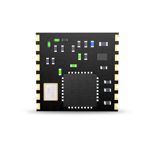
Module Size

Application Connection Diagram

Notice for Pin Connection:
1. PIN9 & PIN10 of DL-P3028M and DL-P3028MPA are the same (ANT, GND), but the position of the pins on the module packaging is different.
2. RX and TX are used for data transmission and should be inversely connected with the UART pins of external MCU.
3. AUX, SETA, SETB and RESET are used for the module control, which need to be connected with the GPIO port ofthe external MCU.
4. SETA and SETB are high level defaulted. When the Wireless Module enters sleep mode, these two Pins need to beconnected to certain levels;otherwise, electric leakage will occur.
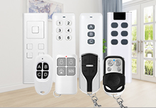
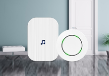
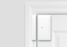
Typical application
Wireless Data Communication, Wireless Remote Control System; Wireless Alarm & Security Control System; Wireless Sensor Networking, Automatic Data Collection; Industrial Remote Control, Intelligent Control System, Home Automation, Smart Building, Smart Home, Smart City, Telemetry, Automatic (Water, Electricity, Gas) Meter Reading;
Product Tags
RF module, Wireless Module, Wireless Transmitter Module, RF Transmitter Module, 433MHz RF Module, Wireless Transceiver Module, FSK Transceiver module, 433MHz Wireless module, PANCHIP, Chirp-IoT™
Brief Introduction
This DL-P3028M RF module is an UART Transceiver Module, which was designed base on high-performance PAN3028 RF chip and built-in HC32L130 low-power MCU. It is an UART Module with AT command, which supports a maximum power output of 22dBm and a sensitivity of -140dBm; it is an effective wireless module which can provide excellent RF performance and strong anti-interference performance in the 398-510MHz frequency band.
Features
● Support AT commands for configuration, easy to develop and debug;
● Support transparent transmission mode for data transmission;
● Support data flow control in transparent transmission mode (AUX);
● Typical serial baud rate (such as 9600/19200/38400/57600/115200bps) is supported;
● Multiple wireless baud rate is supported;
● Wake-on-Radio (WOR) function supported (intermittent receiving), which can be greatly increases the battery standby time;
● Support CAD (Automatic Radio Frequency Signal Detection) to reduce the probability of signal collision;
● Can achieve fixed point transmission, broadcasting and other transmission methods;
Download Center
Typical Application
● Smart Grid and Automatic Meter Reading (water meter, electricity meter, gas meter)
● Long-Range Data Communication
● Smart Home Systems
● Wireless Sensor Networks
● Industrial Automation (Data Acquisition)
● Remote Control and Telemetry of Field Data
● Various Transmitter, Intelligent Flow Meter Instrument
● Building Automation and Security
● Monitoring and Control of Petroleum Equipment in Mines
● Environment, Energy Saving, Temperature Monitoring
● Intelligent Transportation, Smart City
● Home and Building Automation
● Wireless Alarm and Security System
Technical Parameter
No. | Category | Parameter | Value |
1 | Radio Parameter | Working Frequency | 398~510MHz |
2 | Radio Parameter | TX Power | 22dBm (peak value) |
3 | Radio Parameter | RX Sensitivity | -140dBm @SF12 62.5KHz -133dBm @SF9 62.5KHz |
4 | Radio Parameter | Communication Range | (1) >300M@SF7, BW250khz, RF power:22dBm (2) >1500M@SF9, BW125khz, RF power: 22dBm |
5 | Radio Parameter | Antenna Type | External antenna (ANT pad or IPEX) |
6 | Hardware Parameters | Data Interface | Baud rate: 115200 (default) |
7 | Hardware Parameters | Working Voltage | 1.8~3.6V |
8 | Hardware Parameters | Working Current | Receiving: 24mA Sleeping: 1.6uA |
9 | Hardware Parameters | Working Temperature | -40℃ ~ +85℃ |
10 | Hardware Parameters | Storage Temperature | -45℃ ~ +90℃ |
11 | Hardware Parameters | Encapsulation Interface | SMT (surface mount) |
Pin Definitions
| No | Definitions | Type | Description |
| 1 | VIN | PWR | To maximize the chip function, ≥3V stable voltage is recommended |
| 2 | GND | PWR | Reference Ground |
| 3 | ANT | Analog I/O | RF signal input/output port, π-matching circuit must be reserved; Adopt 50Ω impedance matching for RF routing, route the ground and add via holes around it |
| 4 | AUX | Out | Indicate the working status of the module: 0: The buffer is empty 1: Buffer is not empty (Under Transmitting) |
| 5 | UART-RX | In | TTL serial port output, connected to external RXD input pin |
| 6 | UART-TX | Out | TTL serial port output, connected to external RXD input pin |
| 7 | SETA | In | Switching between AT Command and Transparent Transmission Mode, defaulted high level 0: P2P Transmission Mode 1: AT Command Mode |
8 | SETB | In | Control Module Sleep, defaulted high level 0: Sleep (or wake-on-radio) 1: Wake up |
| 9 | RESET | In | Hardware reset |
Module Size
Application Connection Diagram
Notice for Pin Connection:
1. PIN9 & PIN10 of DL-P3028M and DL-P3028MPA are the same (ANT, GND), but the position of the pins on the module packaging is different.
2. RX and TX are used for data transmission and should be inversely connected with the UART pins of external MCU.
3. AUX, SETA, SETB and RESET are used for the module control, which need to be connected with the GPIO port ofthe external MCU.
4. SETA and SETB are high level defaulted. When the Wireless Module enters sleep mode, these two Pins need to beconnected to certain levels;otherwise, electric leakage will occur.
Typical application
Wireless Data Communication, Wireless Remote Control System; Wireless Alarm & Security Control System; Wireless Sensor Networking, Automatic Data Collection; Industrial Remote Control, Intelligent Control System, Home Automation, Smart Building, Smart Home, Smart City, Telemetry, Automatic (Water, Electricity, Gas) Meter Reading;
Product Tags
RF module, Wireless Module, Wireless Transmitter Module, RF Transmitter Module, 433MHz RF Module, Wireless Transceiver Module, FSK Transceiver module, 433MHz Wireless module, PANCHIP, Chirp-IoT™