|


DL-CC2541
BLE4.0
CC2541
10m
15.1*11.2*2
| Quantity: | |
|---|---|
Low-power Bluetooth Module with UART Serial Port Design, Full Duplex Bidirectional Communication
DL-CC2541 is a low-power Bluetooth 4.2 module. This Bluetooth RF module can work in bridge mode (transparent transmission mode) and direct drive mode, it features an universal serial port design, full duplex bidirectional communication. After the BLE module is started, it will automatically broadcast, and the mobile phone that has opened a specific APP will scan and dock it. After success, it can be monitored through the BLE protocol.
In the bridge mode, the user's CPU can communicate with the mobile device through the UART port of the module, and the user can also manage and control certain communication parameters through the specific serial port AT command. The specific meaning of user data is defined by the upper-layer application program. The mobile device can write to the module through the APP, and the written data will be sent to the user's CPU through the serial port. After the module receives the data packet from the user's CPU serial port, it will automatically forward it to the mobile device. In this mode of development, the user must be responsible for the code design of the main CPU and the intelligent mobile APP code design for mobile devices.
In the direct drive mode, the user performs simple peripheral expansion of the module. The APP directly drives the module through the BLE protocol to complete the supervision and control of the module by the intelligent mobile device. In this mode of software development, the user is only responsible for the design of APP codes on the smart mobile device.
Download Center
Features
1. Simple to use, without any Bluetooth protocol stack application experience;
2. The user interface uses a universal serial port design, full duplex bidirectional communication, and the minimum baud rate supports 4800bps;
3. Support bridge mode (serial port transparent transmission) or direct drive mode (no additional CPU required);
4. Default 20ms connection interval, fast connection;
5. Support AT command software reset module to obtain MAC address;
6. Support AT commands to adjust the Bluetooth connection interval and control different forwarding rates. (Dynamic power adjustment);
7. Support AT command to adjust the transmission power, modify the broadcast interval, customize the broadcast data, customize the device identification code, set the data delay (user CPU serial port reception preparation time), modify the serial port baud rate, modify the module name, all will be saved after power off;
8. The length of the serial data packet can be any length below 200 bytes (including 200). (Automatic distribution of large packages);
9. High-speed transparent transmission and forwarding, the fastest up to 4K/S, can work stably in 2.5K-2.8K (IO5, IO6);
10. Support mobile device APP to modify the module name, save after power off, modify the serial port baud rate, product identification code, custom broadcast content, broadcast cycle, all will be saved after power off;
11. Support mobile device APP to reset the module remotely and set the transmission power;
12. Support mobile device APP to adjust the Bluetooth connection interval. (Dynamic power adjustment);
13. Full IO expansion including debug port;
14. Support connection status, broadcast status prompt pin / general IO flexible configuration;
15. Six bidirectional programmable IO, external interrupt trigger input detection, full low power operation. (Trigger alarm, lighting control, remote control toys, etc. various input and output switching applications);
16. Two programmable timed single/cycle inversion output ports. (Smart appointment timing application);
17. Two ADC inputs (14bit), enable/disable, free configuration of sampling period. (Temperature and humidity, photometric and other applications);
18. Four programmable PWM (120Hz) output. (Applications such as dimming and speed control);
19. The RSSI of the module end is continuously collected, readable and can automatically notify the APP, enable/disable, and the collection frequency can be set freely. (Object tracking, Anti-lost alarm application);
20. Support module power prompt, power reading, automatic report. (Device power reminder);
21. Support anti-hijacking password setting, modification and recovery to prevent malicious connections from third parties. It can also not be used. Independent password operation result notification to facilitate APP programming;
22. Support single foot position (long press) for 5 seconds to restore factory settings, APP remote restore factory settings;
23. Support customizing the PWM output initialization state (full high, full low, PWM output state value before power down);
24. Support custom PWM frequency (61.036 Hz<=f<=8 kH z, default 120Hz);
25. Real-time system status of broadcast content prompt module, including battery power, custom device identification code, four-way PWM current output value or acquisition value of two ADCs, current IO status, etc.; (suitable for broadcast application solutions);
26. Two-level pulse width counting, 0~0xFFFFFFFF ms (about 49.7 days);
27. Support internal RTC real-time clock, APP terminal can be synchronized at any time;
28. Support 6-channel IO and 4-channel PWM timing control, this feature is disabled by default;
29. Four-way PWM supports gradient mode (suitable for dimming effect control);
30. Support IO configuration and output state saving function, can customize the default initialization state;
31. Support light recovery and deep recovery modes, flexible recovery of user data, while the reserved product must be configured;
32. Support to get the Bluetooth connection status (connection, normal disconnection and timeout disconnection) string prompt from the TX serial port;
33. Support low level enable mode and pulse width enable mode, support remote shutdown;
34. In pulse enable mode, it supports 30 seconds of automatic shutdown without connection;
35. Under pulse enable mode, support square wave alarm to prompt connection timeout (disconnection)
36. Very low power consumption under standby mode, sleep current from official datasheet (TI-CC2540 chip) is 0.4uA
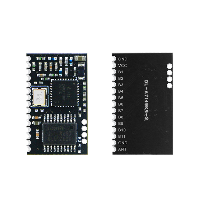
Package and Pin Assignment

| No. | Name | Chip Pin | I/O | Description |
Pin1 | GND | GND | - | Ground |
Pin2 | VCC | VCC | - | Module power supply positive 2V-3.6V |
Pin3 | IO7 | P2.2 | O | Output port (can be flipped regularly) / sleep status indicator |
Pin4 | IO6 | P2.1 | O | Output port (can be flipped regularly)/connection status indication (low level, or square wave prompt, See the chapter "Module Parameter Setting" for details) |
Pin5 | RES | RST | I | Module reset, active low |
Pin6 | EN | P2.0 | I | Module enable control line, the default is level trigger mode Level trigger mode, active low, with internal pull-up. 0: The module starts broadcasting until it connects to the mobile device 1: Regardless of the current state of the module, immediately enter a full sleep state (0.4uA) Pulse trigger mode, every time a pulse is received (W>200ms), the module will switch cyclically between power-on (broadcasting, allowing discovery and connection) and power-off (full sleep state) (For mode switching, please refer to the relevant chapters of "Module Parameter Settings") |
Pin7 | IO5 | P1.7 | I/O | Programmable bidirectional IO, which can be set as input or output through BLE protocol When used as input, it can be used as level pulse width count input terminal |
Pin8 | U+ | USB+ | I/O | CC2541 pin USB+, not used |
Pin9 | U- | USB- | I/O | CC2541 pin USB+, not used |
Pin10 | REST ORE /IO0 | P1.2 | I/O | Factory reset trigger or programmable bidirectional IO Within 30 seconds after power-on, keep this pin low for 5s, the system will restore some parameters (light recovery), if it is maintained for more than 20s, all parameters will be restored (Deep Recovery) (see the chapter of "System Reset and Recovery") 30 seconds after power-on, it can be used as normal IO and can be used through BLE protocol (See "Programmable IO (8 channels) [Service UUID: 0xFFF0]") Set to input or output use |
Pin11 | PWM1 | P1.1 | O | PWM Output channel 1 |
Pin12 | PWM3 | P0.7 | O | PWM Output channel 3 |
Pin13 | PWM4 | P0.6 | O | PWM Output channel 4 |
Pin14 | BRTS | P0.5 | I | As a data sending request (used to wake up the module) 0: The host sends data, and the module will wait to receive data from the host. At this time, the module will not sleep. 1: The host has no data to send, or after the host sends data, this signal line should be set to 1 |
Pin15 | BCTS | P0.4 | O | Data input signal (used to wake up the host, optional) 0: The module has data sent to the host, and the host receives the module data 1: The module has no data sent to the host, or after the module data has been sent, this signal will be set to 1 |
Pin16 | TX | P0.3 | O | Module serial port TX |
Pin17 | RX | P0.2 | I | Module serial RX |
Pin18 | ADC1 | P0.1 | I | Analog quantity acquisition, channel 1 |
Note: Because it is a simplified version with compact size, some IOs are not exported, and the corresponding functions cannot be used. | ||||
Product Tags:
RF modules, Wireless module, BLE Module, Bluetooth Module, RF Transmitter, RF Receiver, 2.4Ghz RF module, RF Receiver module, Wireless Transceiver Module, FSK Transceiver Module, LoRa Module, Bluetooth 5.0 Module, UART Serial Module, Bluetooth Module supplier
Low-power Bluetooth Module with UART Serial Port Design, Full Duplex Bidirectional Communication
DL-CC2541 is a low-power Bluetooth 4.2 module. This Bluetooth RF module can work in bridge mode (transparent transmission mode) and direct drive mode, it features an universal serial port design, full duplex bidirectional communication. After the BLE module is started, it will automatically broadcast, and the mobile phone that has opened a specific APP will scan and dock it. After success, it can be monitored through the BLE protocol.
In the bridge mode, the user's CPU can communicate with the mobile device through the UART port of the module, and the user can also manage and control certain communication parameters through the specific serial port AT command. The specific meaning of user data is defined by the upper-layer application program. The mobile device can write to the module through the APP, and the written data will be sent to the user's CPU through the serial port. After the module receives the data packet from the user's CPU serial port, it will automatically forward it to the mobile device. In this mode of development, the user must be responsible for the code design of the main CPU and the intelligent mobile APP code design for mobile devices.
In the direct drive mode, the user performs simple peripheral expansion of the module. The APP directly drives the module through the BLE protocol to complete the supervision and control of the module by the intelligent mobile device. In this mode of software development, the user is only responsible for the design of APP codes on the smart mobile device.
Download Center
Features
1. Simple to use, without any Bluetooth protocol stack application experience;
2. The user interface uses a universal serial port design, full duplex bidirectional communication, and the minimum baud rate supports 4800bps;
3. Support bridge mode (serial port transparent transmission) or direct drive mode (no additional CPU required);
4. Default 20ms connection interval, fast connection;
5. Support AT command software reset module to obtain MAC address;
6. Support AT commands to adjust the Bluetooth connection interval and control different forwarding rates. (Dynamic power adjustment);
7. Support AT command to adjust the transmission power, modify the broadcast interval, customize the broadcast data, customize the device identification code, set the data delay (user CPU serial port reception preparation time), modify the serial port baud rate, modify the module name, all will be saved after power off;
8. The length of the serial data packet can be any length below 200 bytes (including 200). (Automatic distribution of large packages);
9. High-speed transparent transmission and forwarding, the fastest up to 4K/S, can work stably in 2.5K-2.8K (IO5, IO6);
10. Support mobile device APP to modify the module name, save after power off, modify the serial port baud rate, product identification code, custom broadcast content, broadcast cycle, all will be saved after power off;
11. Support mobile device APP to reset the module remotely and set the transmission power;
12. Support mobile device APP to adjust the Bluetooth connection interval. (Dynamic power adjustment);
13. Full IO expansion including debug port;
14. Support connection status, broadcast status prompt pin / general IO flexible configuration;
15. Six bidirectional programmable IO, external interrupt trigger input detection, full low power operation. (Trigger alarm, lighting control, remote control toys, etc. various input and output switching applications);
16. Two programmable timed single/cycle inversion output ports. (Smart appointment timing application);
17. Two ADC inputs (14bit), enable/disable, free configuration of sampling period. (Temperature and humidity, photometric and other applications);
18. Four programmable PWM (120Hz) output. (Applications such as dimming and speed control);
19. The RSSI of the module end is continuously collected, readable and can automatically notify the APP, enable/disable, and the collection frequency can be set freely. (Object tracking, Anti-lost alarm application);
20. Support module power prompt, power reading, automatic report. (Device power reminder);
21. Support anti-hijacking password setting, modification and recovery to prevent malicious connections from third parties. It can also not be used. Independent password operation result notification to facilitate APP programming;
22. Support single foot position (long press) for 5 seconds to restore factory settings, APP remote restore factory settings;
23. Support customizing the PWM output initialization state (full high, full low, PWM output state value before power down);
24. Support custom PWM frequency (61.036 Hz<=f<=8 kH z, default 120Hz);
25. Real-time system status of broadcast content prompt module, including battery power, custom device identification code, four-way PWM current output value or acquisition value of two ADCs, current IO status, etc.; (suitable for broadcast application solutions);
26. Two-level pulse width counting, 0~0xFFFFFFFF ms (about 49.7 days);
27. Support internal RTC real-time clock, APP terminal can be synchronized at any time;
28. Support 6-channel IO and 4-channel PWM timing control, this feature is disabled by default;
29. Four-way PWM supports gradient mode (suitable for dimming effect control);
30. Support IO configuration and output state saving function, can customize the default initialization state;
31. Support light recovery and deep recovery modes, flexible recovery of user data, while the reserved product must be configured;
32. Support to get the Bluetooth connection status (connection, normal disconnection and timeout disconnection) string prompt from the TX serial port;
33. Support low level enable mode and pulse width enable mode, support remote shutdown;
34. In pulse enable mode, it supports 30 seconds of automatic shutdown without connection;
35. Under pulse enable mode, support square wave alarm to prompt connection timeout (disconnection)
36. Very low power consumption under standby mode, sleep current from official datasheet (TI-CC2540 chip) is 0.4uA
Package and Pin Assignment
| No. | Name | Chip Pin | I/O | Description |
Pin1 | GND | GND | - | Ground |
Pin2 | VCC | VCC | - | Module power supply positive 2V-3.6V |
Pin3 | IO7 | P2.2 | O | Output port (can be flipped regularly) / sleep status indicator |
Pin4 | IO6 | P2.1 | O | Output port (can be flipped regularly)/connection status indication (low level, or square wave prompt, See the chapter "Module Parameter Setting" for details) |
Pin5 | RES | RST | I | Module reset, active low |
Pin6 | EN | P2.0 | I | Module enable control line, the default is level trigger mode Level trigger mode, active low, with internal pull-up. 0: The module starts broadcasting until it connects to the mobile device 1: Regardless of the current state of the module, immediately enter a full sleep state (0.4uA) Pulse trigger mode, every time a pulse is received (W>200ms), the module will switch cyclically between power-on (broadcasting, allowing discovery and connection) and power-off (full sleep state) (For mode switching, please refer to the relevant chapters of "Module Parameter Settings") |
Pin7 | IO5 | P1.7 | I/O | Programmable bidirectional IO, which can be set as input or output through BLE protocol When used as input, it can be used as level pulse width count input terminal |
Pin8 | U+ | USB+ | I/O | CC2541 pin USB+, not used |
Pin9 | U- | USB- | I/O | CC2541 pin USB+, not used |
Pin10 | REST ORE /IO0 | P1.2 | I/O | Factory reset trigger or programmable bidirectional IO Within 30 seconds after power-on, keep this pin low for 5s, the system will restore some parameters (light recovery), if it is maintained for more than 20s, all parameters will be restored (Deep Recovery) (see the chapter of "System Reset and Recovery") 30 seconds after power-on, it can be used as normal IO and can be used through BLE protocol (See "Programmable IO (8 channels) [Service UUID: 0xFFF0]") Set to input or output use |
Pin11 | PWM1 | P1.1 | O | PWM Output channel 1 |
Pin12 | PWM3 | P0.7 | O | PWM Output channel 3 |
Pin13 | PWM4 | P0.6 | O | PWM Output channel 4 |
Pin14 | BRTS | P0.5 | I | As a data sending request (used to wake up the module) 0: The host sends data, and the module will wait to receive data from the host. At this time, the module will not sleep. 1: The host has no data to send, or after the host sends data, this signal line should be set to 1 |
Pin15 | BCTS | P0.4 | O | Data input signal (used to wake up the host, optional) 0: The module has data sent to the host, and the host receives the module data 1: The module has no data sent to the host, or after the module data has been sent, this signal will be set to 1 |
Pin16 | TX | P0.3 | O | Module serial port TX |
Pin17 | RX | P0.2 | I | Module serial RX |
Pin18 | ADC1 | P0.1 | I | Analog quantity acquisition, channel 1 |
Note: Because it is a simplified version with compact size, some IOs are not exported, and the corresponding functions cannot be used. | ||||
Product Tags:
RF modules, Wireless module, BLE Module, Bluetooth Module, RF Transmitter, RF Receiver, 2.4Ghz RF module, RF Receiver module, Wireless Transceiver Module, FSK Transceiver Module, LoRa Module, Bluetooth 5.0 Module, UART Serial Module, Bluetooth Module supplier